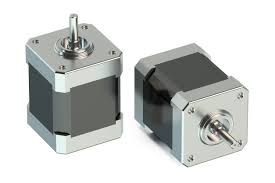
STEPPER MOTOR INTERFACING WITH NODEMCU
In this tutorial, we will learn how to control a Stepper Motor using A4988 Stepper Driver and interface it with NodeMCU. A4988 is a micro-stepping driver used for controlling bipolar stepper motor that has in-built translator for easy operation. Which means we can control stepper motor using 2 pins
Synopsis

In this tutorial, we will learn how to control a Stepper Motor using A4988 Stepper Driver and interface it with NodeMCU. A4988 is a micro-stepping driver used for controlling bipolar stepper motor that has in-built translator for easy operation. Which means we can control stepper motor using 2 pins

Description


Stepper Motor

Stepper motor can divide one complete rotation into a discrete number of steps. These motors are quite similar to switched reluctance motors. Stepper motor makes the motor shaft turn in the specific distance when the pulse of electricity is provided. There are three types of stepper motors they are.

1.Permanent magnet (PM) stepper motor

It uses a permanent magnet in the rotor. It operates based on attraction or repulsion between rotor permanent magnet and stator electromagnetic poles.

2.Variable reluctance (VR) stepper motor

It has a plain iron rotor. When the minimum reluctance occurs with a minimum gap then the rotor points attract to stator magnetic poles.

3.Hybrid Synchronous stepper motor

It is named as hybrid stepper motor because it is a combination of permanent magnet and variable reluctance techniques which is used to achieve maximum power with a small size package.

Based on the stator windings stepper motor is classified into two categories

1.Unipolar Stepper motor

It has two coils with 5or6or8 leads, there one winding with a center tap connection that allows current flow in half winding at a time. Unipolar has less torque and is less efficient


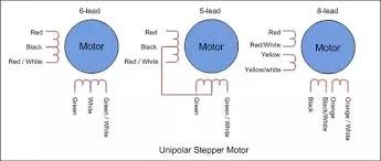
2. Bipolar Stepper motor

It has two coils with 4 leads, there is only single winding per phase that allows current flow through entire winding at a time compared with unipolar stepper motor bipolar stepper motor is more efficient and has more torque.


A4988 Stepper Driver

The stepper driver provides five different step resolutions i.e., full-step, half-step, quarter-step, eight-step, and sixteen-step. It has potentiometer for adjusting the output current.

Pin Configuration of A4988

1. VDD – Provides 3 to 5.5v power supply.

2. Ground

3. 1A,1B – used for connecting one coil of the motor.

4. 2A,2B – used for connecting other coil of the motor.

5. VMOT, GND – used for powering the motor and we need to connect 47uF for protecting the driver voltage.

6. STEP – used to control the movement of the motor.

7. DIR – used to control the direction of the motor.

8. SLEEP – used for minimizing power when motor is OFF.

9. RESET – used to make controller to its initial state.

10. MS1, MS2, MS3 – used for selecting step resolutions.

11. ENABLE – used for turning on and turning off FET output.

NodeMCU

A NodeMCU is a development board with an inbuilt Wi-Fi module in it. It is a basic and cost-efficient board to carry out projects using the internet of things. The NodeMCU has an ESP8266 microcontroller unit in it. The operation of this microcontroller is controlled with the programs used in Arduino thus making it very easier to use and also to learn basic IoT projects. This board has an inbuilt 2.4GHz antenna to receive Wi-Fi functions. This board has a memory of 4mb to store the data acting as ROM and 64Kb of RAM. This board operates at 3.3 volts and it is mandatory to operate the board at this voltage and not more than that as increasing the input voltage in this board may damage few GPIO pins (general input-output pins).


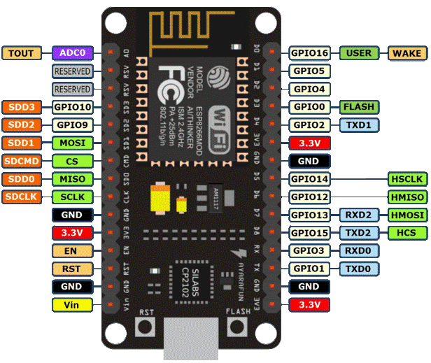
Pin Configuration of NodeMCU

1. Vin: 3.3V can be provided at this pin as the supply to power on the board. This pin is used to power on the entire microcontroller.

2. GND: This pin is connected to the negative terminal of the battery.

3. RST: This pin resets the microcontroller and clears the memory.

4. EN: This pin is used to enable the operation of microcontroller.

5. 3V3: This pin provides 3V output and this can be used to power up some sensor units connected to the microcontroller.

6. SD1, CMD, SD0, CLK: These pins are used in SPI communication, that is it is used to transfer the signals between two microcontrollers, Rx and Tx modules with asynchronous transmission.

7. SD3, SD2: These pins can also function as asynchronous transmission or as GPIO pins.

8. RSV: These are two reserved pins used by the microcontroller and cannot be used in connecting any external circuits to it.

9. A0: This microcontroller only has one analog pin for Analog communication. This A0 pin is used in analog signal communication.

10. GPIO 1 – 16: This controller board has 16 input-output pins which be used as input or output pin based on the programming.

11. GP10 1, 3, 13, 15: This microcontroller has 2 UART communication pins, RX0, TX0 (GPIO 1 & GPIO 3) and RX1, TX1 (GPIO 13, GPIO15).

Schematic


Code

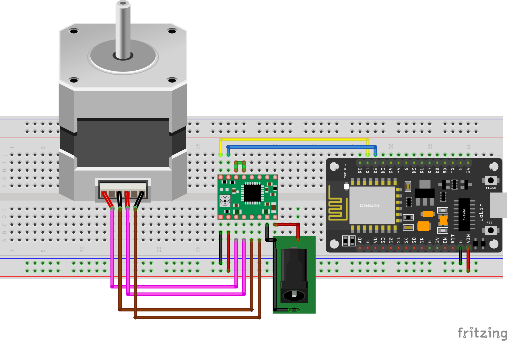
const int stepPin = D2; 
const int dirPin = D1; 
 
void setup() {
  pinMode(stepPin,OUTPUT); 
  pinMode(dirPin,OUTPUT);
}
void loop() {
  digitalWrite(dirPin,HIGH); // SETS THE MOTOR CLOCK-WISE DIRECTION
  for(int x = 0; x < 200; x++) {  // GENERATING 200 PULSES FROM THE CONTROLLER FOR COMPLETE CYCLE
    digitalWrite(stepPin,HIGH); 
    delayMicroseconds(500); 
    digitalWrite(stepPin,LOW); 
    delayMicroseconds(500); 
  }
  delay(1000); 
  
  digitalWrite(dirPin,LOW); // SETS ANTI-CLOCKWISE DIRECTION
  for(int x = 0; x < 200; x++) {  // GENERATING 200 PULSES FROM THE CONTROLLER FOR COMPLETE CYCLE
    digitalWrite(stepPin,HIGH);
    delayMicroseconds(500);
    digitalWrite(stepPin,LOW);
    delayMicroseconds(500);
  }
  delay(1000);
}

Error message here!

Show Error message here!


Forgot your password?

Error message here!

Send OTP

Error message here!

Show Error message here!


Lost your password? Please enter your email address. You will receive a password you Need.

Send Error message here!


Back to log-in

Close